Categories
default embedded systems English articles OpenWrt Tech

Flash memory

Flash in embedded devices is a really hot topic – there are quite some questions which should be asked before choosing the “right” flash memory type. Often the wrong decision turns out to backfire – I experienced this in several projects and companies.
 
Questions which should get asked for evaluating possible flash chips and types are:
 
  •  How many read/write cycles and for which amount of size the flash needs to last without failure?
  •  NOR or NAND flash?
  •  SLC (single cell) or MLC (multi cell) flash?
  •  What about bad blocks and how to deal with them?
  •  How much flash space in spare do I need for my project?
  •  If a filesystem is needed: what kind of filesystem?
Those questions should be dealt with quite carefully when evaluating the right type of flash for a project.
 
Since to most of the above questions there aren’t really simple answers but implications to each other and of course each solution its very own advantages and disadvantages, I’ll try to illustrate some scenarios instead.
 

Erase blocks and erase cycles

 
Flash storage consists of so-called “erase blocks” (just called blocks from now on). Its size highly depend on the kind of flash (NOR/NAND) and the flash total size.
 
Usually NOR flash has much greater blocks than NAND flash – typical block sizes are e.g. 64KB for a 4MB NOR flash, 64KB for a 256MB NAND flash, 128KB for a 512MB NAND flash.
When flash (especially NAND flash) got bigger and bigger in storage size, pages and later sub-pages got introduced.
 
NAND flash consists of erase blocks which might consist of pages which might consist of sub-pages.
 
Though pages and sub-pages can be directly addressed for reading, only whole erase-blocks can be – guess what? – erased.
 
NAND flash also may contain an ‘out of band (OOB) area’ which usually is a fraction of the block or – if any – page size. This is dedicated for meta information (like information about bad blocks, ECC data, erase counters, etc.) and not supposed to be used for your actual data payload.
Flash storage needs to be addressed ‘by block’ for writing. Blocks can only be ‘erased’ for certain times, till they get corrupted and unusable (10.000 – 100.000 times are typical values).
 
Usual conclusion of above is, flash storage can be read but not written byte wise – to write to flash, you need to erase the whole block before. This is not totally wrong, but misleading since simplified.
Flash storage cells by default have the state “erased” (which matches the logical bit ‘1’). Once a bit got flipped to ‘0’ you can only get it back to ‘1’ by erasing the entire block.
 
Even though you can indeed only address the flash “per erase block” for writing – and you have to erase (and therewith write the whole erase block) when intended to flip a bit from ‘0’ to ‘1’ – that doesn’t mean every write operation needs a prior block erase.
Bits can be flipped from ‘1’ to ‘0’ but only an entire block can be switched  (erased) in order to get bits within back to ‘1’.
 
Considering an (in this example unrealistic small) erase block contains ‘1111 1110’ and you want to change it to, let’s say, ‘1110 1111’, you have to:
1) erase the whole block, so it will be ‘1111 1111’
2) flip the 4th byte down to ‘0’
But if we e.g. want to turn ‘1111 1110’ into ‘1010 0110’ we just flip the 2nd, 4th and and 5th bit of the block. That way we don’t need to erase the whole block before, because no bit within the block needs to be changed from ‘0’ to ‘1’.
That way, due to clever write handling of the flash, not every write operation within erase blocks imply erasing the block before.
 
Taking this into account might significantly enhance the lifetime of your flash (especially SLC NAND, MLC requires some even more sophisticated methods), as blocks can only be erased a certain number of times.
It might also allow you to take cheaper flash (with less guaranteed erase cycles).
 
Also you should make sure, that you don’t keep a majority of erase blocks untouched, while others get erased thousands of times.
To avoid this, you usually some kind of ‘wear leveling’. That means, you keep track of how many times blocks got erased, and – if possible – relocate data on blocks, which gets changed often, to blocks which didn’t get erased that often.
To get wear leveling done properly, you need to have certain amount of blocks in spare to be able to rotate the blocks and relocate the actual data properly.

Hardware vs. Software

Both techniques can significantly improve the lifetime of your flash, however require quite some sophisticated algorithms to get a reasonable advantage over not using them.
Bare flash doesn’t deal with those issues. There is controller hardware taking care of that (e.g. in higher-class memory cards / USB sticks), but it usually sucks. If possible, do it in software.
Using e.g. Linux to drive your flash, offers quite some possibilities here (looking at file-systems).

NAND vs. NOR

NOR blocks compared to those of NAND, in relation to the total storage size of the flash, are quite big – which means:
  •  bad write performance (several times slower than on NAND flash)
  •  the very same erase block gets erased far more often and therewith exceed the ‘max. erase cycles’ far easier (in addition: erase cycles are usually about 1000 times less on NOR than on NAND flash)

Bad blocks

Bad blocks and how they’re dealt with decides whether you can use your flash in the end as normal storage or end up in debugging nightmares, caused by weird device failures which might result of improper bad block handling of your flash.
 
A bad block is considered an erase block, which shouldn’t be used anymore because it doesn’t always store data as intended due to bit flips. This means, parts of the block can’t be erased (flipped back to ‘1’ anymore, parts “float” and can’t be get into a well-defined state anymore, etc.). Blocks only can be erased certain amount of times, until they get corrupted and therewith ‘bad’. Once you encounter a probably bad block, it should be marked as bad immediately and never ever be used again.
 
Marking a bad block means: Adding this bad block to a table of bad blocks (which is mostly settled at the end of the flash). Since this table sit within blocks on the flash, which might get bad as well, this table is usually redundant.
 
Bad blocks happen, especially on NAND flash. Even never used NAND flash, right from the factory, might contain bad blocks. Because of that, NAND flash manufacturers ship their flash with “pre-installed” information about which blocks are bad from the beginning. Unfortunately, how this information is stored on the flash, is vendor / product specific. Another common area to store this kind of information the OOB area (if existing) of the flash.
 
This also means, flash of the very some vendor and product, will have a different amount of usable blocks. This is a fact you have to deal with – don’t be too tight in your calculation, you’re going to need space in spare as replacement for bad blocks!

Hardware vs. Software

There are actually NAND chips available doing bad block management by their own. Although I never  used them myself, what I read it sounds quite nice. Most bare flash however doesn’t deal with bad blocks. There might be pre-installed information about bad blocks from the beginning, there might be not. And if there is, the format is what the vendor chose to be the format.
That means, if using a flash controller dealing with bad blocks for you, it needs to be able to read and write the type of format those information are stored in. It needs to be aware about whether the flash has an OOB-areas or not and how they’re organized.
 
There is quite some sophisticated and flexible flash controller hardware out there, but again: if possible, do it in software. There is quite good and proven code for that available.

NAND vs. NOR

NOR flash is way more predictable than NAND flash. NAND flash blocks might get bad whenever they want (humidity, temperature, whatever..).
Reading NAND flash stresses it as well – yes, reading NAND flash causes bad blocks! Although this doesn’t happen as often as due to write operations (and far less on SLC than on MLC flash), it happens and you better deal with it!
The number of expected erase cycles is mentioned in the data-sheets of NAND flashes. The number of read cycles isn’t. However it’s usually something around 10 to 100 times the erase cycles.
Imagine you want to boot from your NAND flash, and the boot-loader – which doesn’t deal yet with bad blocks – sits within blocks which react unpredictable / become bad.. a nightmare!
That’s why it’s common now, that the first few blocks of NAND flash are guaranteed to be safe for the first N erase cycles. Make sure your boot-loader fits into those safe blocks!
Categories
embedded systems English articles OpenWrt Tech

LinuxInput devices (in Qt embedded) – take care!

I’m currently working on an embedded project based on Linux which involves a graphical user interface based on Qt.

In our case Qt accesses framebuffer as well as the LinuxInput devices directly – there is no further layer (DirectFB, Xorg, Wayland, etc.) in between.

In this quite common scenario I noticed that Qt is treating the LinuxInput devices in a quite counterintuitive way which may lead into severe security problems.
The embedded device we are using in this particular project has a keyboard which to the userland is exposed as LinuxInput device.

Everything worked quite well, however our Qt application crashed once due to a programming error (our fault) and I was shown the underlying UNIX console which reflected every single keystroke I did inside the Qt application – all typing input within the Qt application also got passed to other applications / underlying shells!

An exposed root shell to the active TTY – possibly hidden by the GUI – is therewith also capturing all input. Since almost all linux (embedded) distributions are exposing login prompts / shells to all TTYs by default, this scenario is far from being unlikely.

My expected behavior would have been: the Qt application is opening the LinuxInput devices exclusively, so that only the Qt application receives data from the input devices.

After some research and asking around I got pointed to the EVIOCGRAB IOCTL implemented in the LinuxInput subsystem.

As stated in $(LINUX_KERNEL)/include/input/linux.h:

@grab: input handle that currently has the device grabbed (via
EVIOCGRAB ioctl). When a handle grabs a device it becomes sole
recipient for all input events coming from the device

This means: When opening LinuxInput devices they’re not grabbed, they’re not opened exclusively by default.

Okay, I got it 🙂

So let’s just find the magic option / command which tells Qt to set up an EVIOCGRAB with an appropriate argument on the going-to-be-used LinuxInput device. Since I didn’t find any documentation I grep’ed through the Qt source:

> ~/src/qt.git$ git grep EVIOCGRAB
> ~/src/qt.git$

nothing… so I took a closer look into how Qt implemented support for LinuxInput devices (src/gui/embedded/qkbdlinuxinput_qws.cpp) – still nothing…

So I implemented support for telling Qt to open LinuxInput devices exclusively by optionally passing an ‘grab’-argument to the LinuxInput drivers inside Qt.

And here it is – a patch which adds support for passing another parameter named ‘grab’ to the LinuxInput device driver of Qt – to specify whether the device should be opened exclusively (grabbed) or not.

https://dev.openwrt.org/browser/packages/Xorg/lib/qt4/patches/500-allow-device-grabbing.patch?rev=26780

Conclusion: Take care when using Qt and its LinuxInput drivers – all input might be received and used by other applications as well – including shells running on TTYs.


UPDATE: The patch finally git committed and went upstream. Grabbing can now be configured since Qt version 4.8 (http://www.qt.gitorious.org/qt/qt/commit/947aaa79b05adec527c7500e36766c7ff19f118d/diffs)

Categories
embedded systems English articles OpenWrt qi-hardware Tech

RFM12 – kernel patches

Since I got asked several times about the pin mappings and wirings between the rfm12 modules and GPIOs of the devices providing them (in my case the Netgear WGT634U router / the Qi NanoNote) I’d like to try making some things clearer:

In Linux the use of buses is tried to get as abstracted as possible – the idea is that the actual boards (or call it whatever you like as devices, platforms etc) define and expose the capability of buses and its properties.

In our case the rfm12 kernel module requires the availability of an SPI bus – it doesn’t matter how it is implemented (native SPI bus, SPI over GPIOs or any other way of implementation). The client module – the kernel module implementing an driver for the actual rfm12 hardware – simply doesn’t care and doesn’t need to know about that.

That’s the reason why the actual rfm12 code doesn’t contain any GPIO <-> rfm12 hardware mappings – the rfm12 code is just using an existing and otherwise exposed SPI bus.

The actual wiring / mapping and setup of the SPI bus is done within the platform / board / device code, which is located below arch/${ARCH}/${BOARD} – a common place for code like that is arch/${ARCH}/${BOARD}/setup.c.

This project however seemed to have raised some interest and I got asked quite a few times about the board specific changes I made – so here they are now:
the kernel patches which provide SPI buses on both boards, including GPIO mappings.

Since both targets I used the rfm12 module and driver on are running OpenWrt, I created both patches against the Linux vanilla tree having OpenWrt specific kernel patches already applied.

Changes however are small and clear, so they should be easy to understand and adapt.

The wiring I used to get the rfm12 module working on the NanoNote working by the way is the following:


GPIO | PIN on SD port | PIN on module | purpose / description
=====|================|===============|=================================
108  | D12 (1)        | MISO / SDO    | SPI: master input slave output
109  | D13 (2)        | nIRQ          | interrupt
104  | D08 (3)        | (unused)      | (unused)
X    | VDD (4)        | VDD           | power
105  | D09 (5)        | MOSI / SDI    | SPI: master output slave input
X    | VSS (6)        | GND (1+2)     | ground
106  | D10 (7)        | SCK           | SPI: clock
107  | D11 (8)        | nSEL          | SPI: chip select

There needs to be a resistor (10-100kOhm) between pin FSK (if used) of
the rfm12 module and VDD as pullup – however when just using ASK it isn’t needed anyway.

Categories
embedded systems English articles misc OpenWrt Tech

GDB behaves strange while debugging threads

While debugging issues involving binaries on a system running Linux, having a debugger such as GDB available is quite helpful.

However while working on a certain project we recently experienced quite some issues debugging applications involving threads.

Debugging the application on my local workstation worked quite fine, however on OpenWrt-targets – ARM as well as MIPS – it behaved rather strange: stack corruptions, missing traces, weird signals got issued…

After quite some time of debugging the debug issue, we found out the issue is caused by a stripped version of libpthread.so.

Stripped – not in the sense of a more lightweight but compatible version of the pthread library – but stripped by the utility “strip”, which purges all debug- and “other unneeded” symbols out of binaries to reduce their size, which usually is applied on all binaries by the OpenWrt framework automatically.

Usually binaries stripped by “strip” are still fully-fledged binaries, still usable with GDB (however without debugging symbols available of course). Applying strip on libpthread.so* however, it seems to strip out also stuff needed by GDB following and tracing threads. Without these symbols / meta-information not needed for running the actual application, but for tracking its threads, GDB results in mentioned issues above.

One might ask why someone is debugging binaries without debug symbols compiled in – reasons are obvious:

  • there’s not enough storage available
  • there’s not enough RAM available
  • using gdbserver and having the binaries with debug symbols compiled in on another machine communicating with gdbserver

To check whether an object got stripped or not is quite easy using the “file” util:

$ file build_dir/target-arm_v5te_uClibc-0.9.30.1_eabi/root-foo/lib/libpthread-0.9.30.1.so
build_dir/target-arm_v5te_uClibc-0.9.30.1_eabi/root-foo/lib/libpthread-0.9.30.1.so: ELF 32-bit LSB shared object, ARM, version 1 (SYSV), dynamically linked (uses shared libs), stripped

$ file staging_dir/target-arm_v5te_uClibc-0.9.30.1_eabi/root-foo/lib/libpthread-0.9.30.1.so
staging_dir/target-arm_v5te_uClibc-0.9.30.1_eabi/root-foo/lib/libpthread-0.9.30.1.so: ELF 32-bit LSB shared object, ARM, version 1 (SYSV), dynamically linked (uses shared libs), not stripped

Long story short: When debugging applications involving threads, always use a non-stripped version of libpthread.so, even if debug symbols are not needed!

Categories
embedded systems English articles OpenWrt qi-hardware Tech

Ben NanoNote able to control radio power sockets

The Ben NanoNote is now able to switch radio controlled power sockets, too!

The rfm12 433MHz module, produced by HopeRF,  is attached to the microSD port of the Ben NanoNote, which pins are exposed via an microSD card dummy adapter.

rfm12 module attached to a microSD dummy

The System-on-a-chip used inside the Ben NanoNote (ingenic JZ47XX) allows us to put the microSD pins into GPIO mode, so we can (as already done for the first device, the Netgear WGT634u router, I connected an rfm12-module to) create and export an SPI bus on top of them to be able communicating with the module.

That way there’s no need of opening the device and/or soldering anything anywhere – the module is attached directly to the microSD dummy which gets simply inserted into microSD slot of the NanoNote.

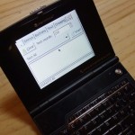
rfm12 module attached to NanoNote running ncurses UI for switching power sockets

I wrote a basic but fully working ncurses frontend using the rfm12 library listing configured devices waiting for getting switched.

There’s also a ready-to-use XMLRPC daemon available which exposes all configured devices and provides functions for controlling them, so UIs for controlling devices are not limited to run on the same system the rfm12 module is installed on.

ncurses UI for switching configured radio controlled power sockets on the Ben NanoNote

I’ve also written a little GUI in python using the qt4 toolkit, connecting to the master via XML-RPC:

switching radio controlled power via a GUI using pyqt4

Several other frontends are work-in-progress as e.g. a GUI for the Android platform, as well as one based on qt4/QML being able to run e.g. on phones running Meego/Maemo as operating system – both using the XML-RPC interface.

So all major parts of the project are mostly finished now and the API is more or less fix.

The the whole project now consists of (a rough overview):

  1. the kernel module which communicates with the actual hardware (so the rfm12 module) and exposes a character device to userspace
  2. the rfm12 library which
    • connects to the kernel module
    • contains the device type specific data and code to modulate signals which control the actual power sockets
    • provides functions for reading / writing configuration files and controlling / switching devices
  3. applications using the library and its functions for actual controlling of devices, which could be / already are:
    • UI applications linked directly against librfm12 (an ncurses frontend (shown above) is available yet)
    • daemons providing network interfaces (a daemon exporting functionality via XMLRPC is available yet , one doing the same but using JSON-RPC as underlying rpc method is going to be implemented soon)
  4. UIs running on different machines, using these RPC services  (e.g. above pyqt4  frontend; android- and qml-frontends are work-in-progress)

Devices are getting configured via configuration files, describing the product type of the device, a name and the actual code which is used to identify devices of a certain product type group.

The config used by the applications shown on the photos / screenshots above just looks this:

[socket_A]
label = “one”
product = “P801B”
code = “1111110000”
[socket_B]
label = “two”
product = “2272”
code = “1111110000”
[socket_C]
label = “three”
product = “2272”
code = “1111101000”

One of the tasks I’m working on right now, is state sharing. While the list of configured devices and it’s states (on/off) is already shared among all XML-RPC clients (so having switched a unit in one client, others will fetch the changed state next time they poll/refresh), the state is not yet shared between several processes invoking the librfm12.

Issue is: Every process linked against librfm12 creates its own list of devices, including states – so every process has its own copy. Changes done in one process are not shared among others. This could be solved using IPC (System V shared memory, sockets every instance connects to, etc.).

That’s it – feedback and/or participation is highly appreciated!


Ben NanoNote having an rfm12 module attached via microSD-port and several types of radio controlled power sockets

Source Code is still available on github: https://github.com/mirko/rfm12-ASK-for-linux 🙂

Categories
embedded systems English articles OpenWrt qi-hardware Tech

RFM12 under Linux and remote controlled power sockets

Currently I’m working on a project communicating and transmitting signals over the air with an 433 MHz radio module called “rfm12“, produced by HopeRF, soldered onto devices capable of running OpenWrt and having at least 3 accessible GPIO’s.

Short story long:

These radio modules are capable of sending / receiving over the ISM frequency band, as e.g. 433 MHz or 868 MHz and just cost about 5 Euros.

RFM12 module
RFM12 module soldered onto eval board

The idea was to get the module working on several embedded boards running Linux, e.g. routers, microcomputers such as the NanoNote, etc. via a generic software interface.

The rfm12 module is controlled via the 4-wire protocol SPI which basically is based on toggling pins between the machine’s logic-levels (high/low) at an individual non-specified clock-speed (http://en.wikipedia.org/wiki/Serial_Peripheral_Interface_Bus).

Since most of mentioned boards do not own a native SPI bus, but several GPIO’s (most LED’s are connected via GPIO’s on such devices), SPI can be “emulated” by toggling these GPIO’s in a specific way (also called “bitbanging“).

That way there’s no need for any other electronic peripherals such as microcontrollers, semiconductors, resistors, etc. – the chip is directly connected with the board – everything is done in software.

Inspired by the project “ethersex” – a project programming and maintaining a software for Atmel AVR micro-controllers used for home- / building automation – and an approach of soldering the module onto a specific router, communicating via SPI over GPIO’s (however used code is rather old, unmaintained and board-specific)  – the idea came up to write a generic linux kernel module to support the module from within linux directly.

Based on the ideas realised with the ethersex project, I decided to aim my project on being able to switch remote controlled power sockets of which I own several (to each other incompatible) modules.

Because the rfm12 module is (only) capable of doing FM (modulating payload data on top of the frequency), but lot’s of devices are controlled via AM (most remote controlled power sockets included), we emulate AM by simply turning the module on and off in a specific sequence.

Since this operation is timing critical and needs to be atomic, we need to do basic stuff in the kernel space rather than from userspace.

The whole project is going to consist of 4 major parts:

  • the rfm12 driver as kernel module which provides an API (accessible via a character device) to the userspace
  • an userspace library which contains all the information and protocol (meta)data for such remote controllable devices, providing an (more or less) generic interface and configuration of devices
  • an actual application using the library, so controlling the devices – maybe exporting the available functions via RPC (json, xml, etc.) to provide network access
  • a remote usable UI (for mobile devices as phones (android/meego), web-related, qt/gtk…)

My testing device is an old Netgear WGT634U I had in spare which has a broadcom 47xx SoC working in and 4 unused GPIO’s available.

RFM12 module directly connected to a Netgear WGT634U router

Implemented yet is support for the most common radio controlled sockets sold – the ones which have a 2272/2262 IC built in (including these Chinese versions which get on fire – http://ec.europa.eu/consumers/dyna/rapex/create_rapex.cfm?rx_id=142 #25) and the ones using an P801B chip.

radio controlled power sockets: 2272, P801B, 2262

I also have a set of radio controlled dimmers which protocol I’m going to implement soon…

For now the source code is hosted on github: https://github.com/mirko/rfm12-ASK-for-linux – there’s no project site yet but will be created if the project is growing / interest is getting raised 🙂

UPDATE: In case you’re willing to participate, you’re more than welcome! Just drop me an email… There’s lot’s of stuff I’d like to see implemented, especially usable (G)UI’s… but for sure it’s not just about me: patches, feedback, enhancements and feature-requests (in a certain extent) are highly appreciated!

Categories
Bali (Indonesia) Brussels (Belgium) Dalian (china) embedded systems English articles fun German articles misc My life Openmoko OpenWrt qi-hardware Taipei (Taiwan) Tech Trips Windows Mobile

comments, twitter…

I recognized just a few hours ago, there were comments written, which needed to be approved…

Did so now and tried to respond to them – sorry for the delay and thanks a lot for your input/contributions!

As most people reading my blog do know already anyway and I no longer feel ashamed of using it…

My twitter username: foobarbablub – respectively the twitter page: http://twitter.com/foobarblablub

Polluting the twitter cloud with statements / impressions I don’t think they’re worth a whole blog post… most tweets are not related to technical / computer stuff by the way – used language is mostly English…

Categories
Bali (Indonesia) embedded systems English articles My life OpenWrt qi-hardware Tech Trips

trip trip – hurra!

Long time no news…

some things happened which weren’t worth a particular post (or I was just too lazy), so I’ll try to summarize of a few things which happen(ed):

== tech stuff

OpenWrt is still my focus – the qt4 package now got libX11 support (besides DirectFB / linuxfb, both accessed by the QWS-part) – thanks a lot to Michael Büsch at this point!

I’m also very interested in the new features of qt4.7 – especially the declarative UI part of qt4.7 called QML – an approach of designing UIs in a declarative way, means, from the UI’s point of view (more in the mentioned links above).

I’m curious about how/whether it can/will be used/accepted by “native” designers to write fully functional GUI applications.

It’s approach is looking quite promising to me – the language style as well as the implementation – really curious about how it’ll do on embedded devices without graphics acceleration. After some talks to qt developers GL support is not required; a number of animations, effects and transitions were optimized for software processing and should be even smoother than rendered via GL.

First usecase is going to be a picture frame, which has the same SoC built in (Ingenic JZ4740) as the NanoNote and therewith is pretty well supported.

The picture-frame is an ID800WT manufactured by Sungale.

Before somebody is going to think, whether I want to promote/support/recommend this brand/product:

From the board layout’s point of view it is the worst product sold in Germany I’ve ever seen! And it’s too expensive! And the company violates the GPL!

Take a look at the board by yourself:

Sungale pictureframe ID800WT board

The USB Wifi-stick got hot-glued onto the board, it seems they even unsoldered the USB-socket manually (because it looks really charred all around) and connected it with some random wires to a SMD-chip which in fact is an USB-hub. Around there’s hot-glue all around, partially charred, partially way too much. This is really the worst in Germany sold product ever!

However it serves the purpose – has supported wifi (atheros), an 800×600-display, a touchscreen, USB-host, etc.

After my holidays I’ll try to evaluate and play around with qt4.7-features on that device on top of OpenWrt.

== trips

After almost one week spent in Croatia, Split, participating at the “nothing will happen” conference – which was really amazing and organized by very nice people – I’m going to travel to Bali for one month, leaving in two days.

Actually I wanted to go to Burma (Myanmar), however I mixed them up and booked my flight to Bali, Indonesia… anyway – more beach and sea this time…

This is going to be my third trip to Asia and I’m really looking forward to it – this time for holiday, backpacking without any fixed plans.

Actually I also didn’t want to take a computer with me – still I bought an EeePC 1015. Resolution is disappointing, however price, weight, battery life (about 8 fucking hours!) and site serve the purpose of just having a terminal perfectly.

See you there 🙂

Categories
embedded systems English articles OpenWrt qi-hardware Tech

QT/KDE on OpenWrt

As you may know OpenWrt’s collection of ported packages is continuesly growing.

Many graphical stuff gets ported, as well as graphical desktops and toolkits (lxde, xfce, gnome based on GTK2 – e17 based on the enlightenment foundation libraries – etc.).

However there was no approach yet to port the last missing Desktop “KDE” and underlying Toolkit “QT”.

That’s why I went to “Tokamak 4” this weekend, a meeting organized and founded by the KDE foundation, intended to communicate and hack together related to several KDE software projects.

We were about 25 people from all over the world and I really enjoyed the stay and nice, friendly and mixed party – surprisingly I was the only one not using KDE (however not for a special reason – just got used to my current environment) :).

They showed lot’s of interest in the UCI-System (Unified Configuration Interface) OpenWrt is using.
It’s a simple, human-readable, easy-to-parse configuration file format and library OpenWrt uses for services to make it easy writing Administration Interfaces for them (e.g. the webinterface “LuCI”).
We were spinning around about KDE Plasma applets which will list available OpenWrt-devices ready to get administrated right through native applications.

Key deal for me however was to get in touch with people who know the QT/KDE architecture very well, for sure promoting a bit OpenWrt, qi-hardware and it’s concept of open hardware and why I think having QT/KDE support within OpenWrt is opening lot’s of opportunities for both projects.

Since QT is able to use DirectFB (a very powerful but light abstraction for the linux framebuffer) – and therefore does not require a X11 system necessarily – it would be also great for limited hardware such as the Ben NanoNote (32MB of RAM) where I got GTK2-based apps running on top of DirectFB quite some time ago.

I expected to get basic support for QT within OpenWrt done this weekend, however I underestimated the size and complexity of QT – never touched QT-code before.
I realized QT is not just a toolkit as GTK2 is, but a whole framework which tries to abstract as much as possible from the underlying system. It features own backends for multimedia, sound, graphics, even networking – to achieve a stable API and platform compatibility without the need of code modifications, no matter which backends or systems are used below.

In which way the typical issues of such a abstraction-concept – such as getting bloated, having performance issues, being feature-limited as you’re usually just able to support the least common denominator of all supported backends, etc. – I’ve no idea yet – maybe they found a way, will find that out sooner or later.

They also use “qmake” as build-system which is structured quite different than e.g. GNU make, so this got another temporary road blocker as I used qmake never before and had to dig in first.

Back to the port of QT to OpenWrt: I’m having promise to see the first basic QT based application running on a OpenWrt supported device within the next days.

Will let you know 🙂

Categories
embedded systems Openmoko OpenWrt qi-hardware Tech

GTK2 running on top of DirectFB on OpenWrt!

OpenWrt is now able to run applications based on toolkit GTK+ on top of DirectFB!

Using DirectFB avoids having a full blown X11-server (most times Xorg) running, but having the possibiliy of getting nice GTK2 widgets onto your display without altering applications which are using the toolkit.

I was quite happy I got that working, because unfortunately DirectFB-support on part of gtk2 is quite broken in most versions.

Due its incredible slowness of GTK2 on the Openmoko Freerunner (400 MHz ARM, 128 MB RAM) I didn’t expect much of gtk2 on top of DirectFB.

Surprisingly, a simple gtk2 app runs quite well and responsive on my Ben NanoNote by qi-hardware (366 MHz mips, 32 MB RAM).

I was curious and started some benchmarking with the gtk2 performance testing tool “gtkperf”. However I had to patch gtkperf that it’ll be usable with the qvga-resolution on the Ben NanoNote (otherwise parts of the app were hidden and the benchmark will get falsified because not the whole gets redrawed).

Do not compare your results of an original version of gtkperf with mine – varieties may be caused due to mentioned changes! (Patch: http://nanl.de/files/patches/gtkperf/gtkperf-adjust-layout.patch)

What got tested?

gtkperf using GTK2 on:

  1. Openmoko Freerunner with DirectFB
  2. Openmoko Freerunner with Xorg and glamo driver
  3. Openmoko Freerunner with Xorg and fbdev driver
  4. qi-hardware Ben NanoNote with DirectFB
  5. qi-hardware Ben NanoNote with Xorg and fbdev driver (not yet done)
1 2
GtkEntry – time: 0.91
GtkComboBox – time: 16.01
GtkComboBoxEntry – time: 10.18
GtkSpinButton – time: 2.37
GtkProgressBar – time: 1.04
GtkToggleButton – time: 2.54
GtkCheckButton – time: 1.72
GtkRadioButton – time: 4.16
GtkTextView – Add text – time: 9.47
GtkEntry – time: 2.08
GtkComboBox – time: 30.40
GtkComboBoxEntry – time: 21.65
GtkSpinButton – time: 3.54
GtkProgressBar – time: 2.55
GtkToggleButton – time: 4.66
GtkCheckButton – time: 2.71
GtkRadioButton – time: 6.64
GtkTextView – Add text – time: 26.06
3 4
GtkEntry – time: 1.73
GtkComboBox – time: 22.70
GtkComboBoxEntry – time: 16.52
GtkSpinButton – time: 2.60
GtkProgressBar – time: 1.93
GtkToggleButton – time: 3.60
GtkCheckButton – time: 2.28
GtkRadioButton – time: 5.73
GtkTextView – Add text – time: 18.81
GtkEntry – time: 1.07
GtkComboBox – time: 18.61
GtkComboBoxEntry – time: 10.98
GtkSpinButton – time: 2.81
GtkProgressBar – time: 1.51
GtkToggleButton – time: 4.31
GtkCheckButton – time: 2.60
GtkRadioButton – time: 7.42
GtkTextView – Add text – time: 12.48


The results are really interesting!

On the Openmoko GTA02 (Freerunner) GTK on DirectFB seems to be almost twice as fast as GTK on top of Xorg!

Even though the Hardware of the Ben NanoNote is quite limited compared to the GTA02, the benchmark looks quite promising and GTK2-applications seem to be – unline I expected – really usable on that kind of limited hardware.

What’s really confusing to me: running gtkperf on top of the accelerated Xorg-glamo driver for the glamo graphics chip is slower than using the not accelerated Xorg-fbdev driver. However this myth should not be part of this article; I’ll get in touch with Lars – the author of Xorg-glamo – regarding this issue.

UPDATE: Lars told me this is related to the glamo-overhead. Data transferred to the framebuffer via fbdev only consists of pure pixmap-data. Data transferred via the glamo-driver consists of data AND special glamo-related commands (telling the chip what to accelerate) which results in more data to be transferred. Normally this shouldn’t cause such a discrepancy, however the glamo memory-onnection is a bottleneck and only capable of tansferring around 4 MB / second which slows down unacceleraed content. The glamo chip provides the interface for the SD-card, so the whole bus is shared by graphics- and SD-carc-traffic. That’s the reason why e.g. playing videos (unaccelerated) stored on SD-card is that damn slow!

Further tests, benchmarks, evaluation coming soon…

Versions:

gtkperf: 0.40 (with patch: http://nanl.de/files/patches/gtkperf/gtkperf-adjust-layout.patch)
DirectFB: 1.4
GTK+: 2.17.0
cairo: 1.8.6
pango:1.26.0
freetype: 2.3.9
glib: 2.22.2
atk: 1.22.0
pixman: 0.14.0
Xorg X11 server: X11R7.4-1.5.1
xorg-driver-glamo: b45d78c927715b8814404fc2a34ae0aa1d003c29